Environmental Report 2012
Special Feature: Responses to the Amended Water Quality Pollution Control Act
The company has strengthened its approach to preventing contamination of ground water in response to the recent revision of Japan's Water Quality Pollution Control Act. The JAE Group has implemented many measures to prevent contamination to date, and this section also reviews our earlier measures to comply with the Act. As described below, even our past efforts have closely conformed with the content of the amendments to the Water Quality Pollution Control Act.(1) Guidelines for the Prevention of Environmental Pollution (JAE Group)
Between FY 2009 and 2010, the JAE Group identified facilities requiring measures to prevent environmental pollution, evaluating and classifying the substances used and state of the installations. All facilities of domestic group companies were covered with common standards, and the Guidelines for the Prevention of Environmental Pollution were compiled in FY 2011 based on the results.
The company determined that preventive measures for buried piping should be given a high priority, and as was explained in last year's environmental report, the piping is gradually being brought above ground with the addition of double piping.The guidelines incorporate the amended Water Quality Pollution Control Act as far as possible, and the company plans to reflect the actual measures it takes in the guidelines and further enhance their content.
(2) Measures against leakage from acid/alkali effluent tanks and piping (SAE)
These efforts are for the treatment of waste acid and alkali generated in the chemical treatment process at SAE. Circulating water from the scrubbing tower is stored in the effluent tank, and low concentration effluent is collected via the double piping (Figure A).
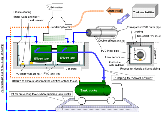
1) Underground waste tank room (Figure A, top left)
There are two cylindrical effluent tanks side by side, each in a square tray made of PVC. These are located underground, enclosed in concrete coated with plastic. The bottom and sides are covered in PVC which is welded at the joints, with leak sensors in the bottom. It is easiest to think of it as effluent tanks placed on trays in a big PVC box.
2) Recess for double effluent piping (Figure A, center right)
Effluent from the treatment facilities can be checked visually by looking at the double piping, the outer tube of which is transparent PVC, and also with the detection function provided by leak sensors in the outer tube. This double piping is housed in a U-shaped trough of welded PVC so that contamination from leaks is prevented by several layers of protection.
3) Pit for preventing leaks when filling tank trucks (Figure A, center bottom)
Effluent from the effluent tanks is shipped out by tank truck. The tank truck is parked in a pit so that if a leak should occur when the truck is being filled, the leaked effluent can be recovered from the pit and returned to the effluent tank. Furthermore, in order to prevent the atmospheric release of exhaust including hazardous constituents from the cavities of the tank truck which occur in the course of routine work, a flexible tube for collection of gas is connected to the scrubbing tower.
(3) Effluent piping system with provisions for damaged pipes, leak detection, inspection and more (JAE)
Although this was mentioned in the environmental report for FY 2007, these measures were taken in response to the leakage of fluorine from damaged effluent piping that occurred in February 2006. With the latest amendment of the Water Quality Pollution Control Act, this is a valuable example of measures to strengthen inspection and monitoring for the prevention of contamination.
1) U-bend
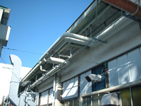
Investigation of the cause of the damage to the piping indicated that stress due to thermal expansion and contraction of the piping had a significant impact, therefore the pipes were rerouted away from direct sun light and the double piping was provided with thermal insulation. Furthermore, U-bends were added to long straight sections of piping to relieve stress as shown in Photograph 02, designed with a sufficient safety index for the bending strength of the piping material.
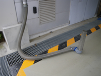
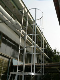
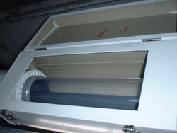
2) Leak monitoring window
Since the effluent piping is installed beneath the eaves of the manufacturing facility building, a ladder is used for checking the leak monitoring window as shown in Photograph 03. A cage is installed to ensure that the work can be carried out safely. As shown in Photograph 04, the leak monitoring window affords a view through the transparent PVC outside piping, enabling checks for leaks.
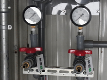
3) Check for leaks in the double piping using pressure testing
Leak sensors are located appropriately within the double piping, but pressure testing is also used as an effective check of the reliability of the pipes. As shown in Photograph 05, special valves and pressure gauges are built in to enable periodic internal pressure tests.
(4) Anticipating the amended
Water Quality Pollution Control Act (HAE)
HAE is the JAE Group's main domestic production plant with facilities specified in the Water Quality Pollution Control Act (plating facilities). As such, it is provided with plating facilities, pits, trenches, indoor and outdoor chemical tanks and ancillary facilities that were initially built in 1982 with materials and construction methods for preventing leaks. These conform to the structural standards in the amended Water Quality Pollution Control Act. Furthermore, the new waste water processing building expanded in FY 2010 has all of its piping above ground, with additional measures taken (Photograph 06).
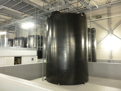
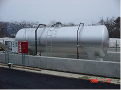
(5) Removing buried fuel tanks and installing new above-ground tanks (JAE, YAE, FAE)
When the No. 2 Plant was built at YAE in 2006, the 10 kl fuel oil tank for space heating was installed above ground in order to prevent groundwater and soil contamination (Photograph 07). In addition, the air conditioning system at the No. 1 Plant was switched to a heat pump system from FY 2010 to 2012 and two underground fuel oil tanks for space heating with a total capacity of 20 kl were removed. Likewise when the new JAE No. 5 Plant was switched to city gas, the two underground fuel oil tanks for the old plant, with a total capacity of 11.9 kl, were removed. The air conditioning at FAE was also switched to a system without boilers from FY 2011. As a result of this change, one of the 5 kl underground tanks is no longer in use.
Photograph 07: Aboveground fuel oil tank at YAE
These initiatives tend to draw attention for their contribution to preventing climate change, but they are also noteworthy for their role in preventing contamination of ground water.